
Cisco Nexus 7000 and Nexus 7700, these modular switches deliver full NX-OS features and open-source programmable tools for software-defined deployments. Get high-density 10, 40, and 100 Gigabit Ethernet with application awareness, high programmability, and performance analytics.
- The Nexus 7000 Series switches form the core data center networking fabric. They can provide an end-to-end data center architecture on a single platform, including data center core, aggregation, and access layer.
- There are multiple chassis options from the Nexus 7000 and Nexus 7700 product family.
- The modular design of the Nexus 7000 and Nexus 7700 enables them to offer different types of network interfaces—1G, 10G, 40G, and 100G—in a high-density, scalable way with a switching capacity beyond 15 Tbps for the Nexus 7000 Series and 83 Tbps for the Nexus 7700 Series.
- The Nexus 7000 hardware architecture offers redundant supervisor engines, redundant power supplies, and redundant fabric cards for high availability. It is very reliable by supporting in-service software upgrades (ISSUs) with zero packet loss. It is easy to manage using the command line or through data center network manager; you can utilize NX-OS APIs to manage it.
Nexus 7000 and Nexus 7700 Modular Platform Comparison
| 7004 | 7009 | 7010 | 7018 | 7706 | 7710 | 7718 | |
| Supervisor Redundancy | Yes | Yes | Yes | Yes | Yes | Yes | Yes |
| I/O Module Slots | 2 | 7 | 8 | 16 | 4 | 8 | 16 |
| Bandwidth per Slot | 440 Gbps | 550 Gbps | 550 Gbps | 550 Gbps | 1.3 Tbps | 1.3 Tbps | 1.3 Tbps |
| Switching Capacity (Tbps) | 1.92 | 7.7 | 8.8 | 17.6 | 21 | 42 | 83 |
| 1GE Port Density | 96 | 336 | 384 | 768 | 192 | 384 | 768 |
| 10GE Port Density | 96 | 336 | 384 | 768 | 192 | 384 | 768 |
| 40GE Port Density | 24 | 84 | 96 | 192 | 96 | 192 | 384 |
| 100GE Port Density | 4 | 14 | 16 | 32 | 48 | 96 | 192 |
| Rack Space (RU) | 7 | 14 | 21 | 25 | 9 | 14 | 26 |
| Airflow | Side-rear | Side-side | Frontback | Side-side | Frontback | Frontback | Frontback |
The Nexus 7000 and Nexus 7700 product family is modular in design with great focus on the redundancy of all the critical components; this has been applied across the physical, environmental, power, and system software aspects of the chassis.
- Supervisor module redundancy: The chassis can have up to two supervisor modules operating in active and standby modes. State and configuration are in sync between the two supervisors, which provide seamless and stateful switchover in the event of a supervisor module failure.
NOTE: There are dedicated slots for the supervisor engines in all Nexus chassis; the supervisor modules are not interchangeable between the Nexus 7000 and Nexus 7700 chassis.
- Switch fabric redundancy: The fabric modules support load sharing. You can have multiple fabric modules; the Nexus 7000 supports up to five fabric modules, and Nexus 7700 supports up to six fabric modules. With the current shipping fabric cards and current I/O modules, the switches support N+1 redundancy.
NOTE: The fabric modules between the Nexus 7000 and Nexus 7700 are not interchangeable.
- Cooling subsystem: The system has redundant fan trays. There are multiple fans on the fan trays, and any failure of one of the fans will not result in loss of service.
- Power subsystem availability features: The system will support the following power redundancy options:
- Combined mode, where the total power available is the sum of the outputs of all the power supplies installed. (This is not redundant.)
- PSU redundancy, where the total power available is the sum of all power supplies minus 1, otherwise commonly called N+1 redundancy.
- Grid redundancy, where the total power available is the sum of the power from only one input on each PSU. Each PSU has two supply inputs, allowing it to be connected to separate isolated A/C supplies. In the event of an A/C supply failure, 50% of power is secure.
- Full redundancy, which is the combination of PSU redundancy and grid redundancy. In most cases, this will be the same as grid mode but will assure customers that they are protected for either a PSU or a grid failure, but not both at the same time.
- PSU redundancy is the default.
- Modular software upgrades: The NX-OS software is designed with a modular architecture, which helps to address specific issues and minimize the system overall impact. Each service running is an individual memory-protected process, including multiple instances of a particular service that provide effective fault isolation between services and that make each service individually monitored and managed. Most of the services allow stateful restart, enabling a service that’s experiencing a failure to be restarted and resume operation without affecting other services.
- Cisco NX-OS in-service software upgrade (ISSU): With the NX-OS modular architecture, you can support ISSU, which enables you to do a complete system upgrade without disrupting the data plane and achieve zero packet loss.
- Cable management: The integrated cable management system is designed to support the cabling requirements of a fully configured system to either or both sides of the switch, allowing maximum flexibility.
- System-level LEDs: A series of LEDs at the top of the chassis provides a clear summary of the status of the major system components. The LEDs alert operators to the need to conduct further investigation. These LEDs report the power supply, fan, fabric, supervisor, and I/O module status.
- Cable management: The cable management cover and optional front module doors provide protection from accidental interference with both the cabling and modules that are installed in the system. The transparent front door allows observation of cabling and module indicator and status lights.
Nexus 7000 and Nexus 7700 have multiple models with different specifications. Figure 1-18 shows these switching models, and Table 1-5 shows their specifications.
Figure 1-18 Cisco Nexus 7000 and Nexus 7700 Product Families

NOTE: When you go through Table 1-5, you might wonder how the switching capacity was calculated. For example, the Nexus 7010 has eight line cards slots, so the calculation is
(550 Gbps/slot) × (8 payload slots) = 4400 Gbps, (4400 Gbps) × (2 for full duplex operation) = 8800 Gbps = 8.8 Tbps system bandwidth
For the Nexus 7700 Series, we’ll use the Nexus 7718 as an example. Although the bandwidth/slot shown in the table gives us 1.3 Tbps, the Nexus 7700 is capable of more than double its capacity, and that can be achieved by upgrading the fabric cards for the chassis. Therefore, if the bandwidth/slot is 2.6 Tbps, the calculation is
(2.6 Tbps/slot) × (16 payload slots) = 41.6 Tbps, (4400Gbps) × (2 for full duplex operation) = 83.2 Tbps system bandwidth
In some bandwidth calculations for the chassis, the supervisor slots are taken into consideration because each supervisor slot has a single channel of connectivity to each fabric card, so that makes a total of five crossbar channels.
So, for example, the Cisco Nexus 7010 bandwidth is being calculated like so:
(550 Gbps/slot) × (9 payload slots) = 4950 Gbps, (4950 Gbps) × (2 for full duplex operation) = 9900 Gbps = 9.9 Tbps system bandwidth
Using this type of calculation, a 9-slot chassis will have 8.8 Tbps, and the 18-slot chassis will have 18.7 Tbps.
Cisco Nexus 7004 Series Switch Chassis
Key Topic
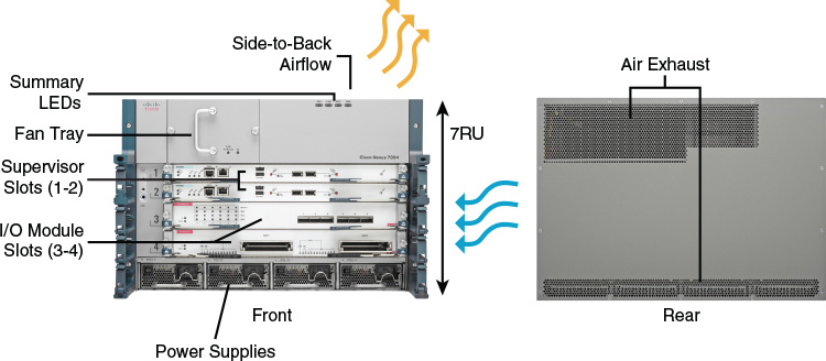
The Cisco Nexus 7004 switch chassis shown in Figure 1-19 has two supervisor module slots and two I/O modules; the complete specification for the Nexus 7004 is shown in Table 1-5. It is worth mentioning that the Nexus 7004 doesn’t have any fabric modules; the local I/O module fabrics are connected back-to-back to form a two-stage crossbar that interconnects the I/O modules and the supervisor engines. It has one fan tray and four 3kW power supplies.
Figure 1-19 Cisco Nexus 7004 Switch
Cisco Nexus 7009 Series Switch Chassis
The Cisco Nexus 7009 switch chassis shown in Figure 1-20 has two supervisor module slots and seven I/O module slots; the complete specification for the Nexus 7009 is shown in Table 1-5. The Nexus 7009 switch has a single fan tray. The fan redundancy is two parts: individual fans in the fan tray and fan tray controllers. The fan controllers are fully redundant, reducing the probability of a total fan tray failure. The fans in the fan trays are individually wired to isolate any failure and are fully redundant so that other fans in the tray can take over when one or more fans fail. So, there is redundancy within the cooling system due to the number of fans. If an individual fan fails, other fans automatically run at higher speeds, and the system will continue to function, giving you time to get a spare and replace the fan tray.
Figure 1-20 Cisco Nexus 7009 Switch
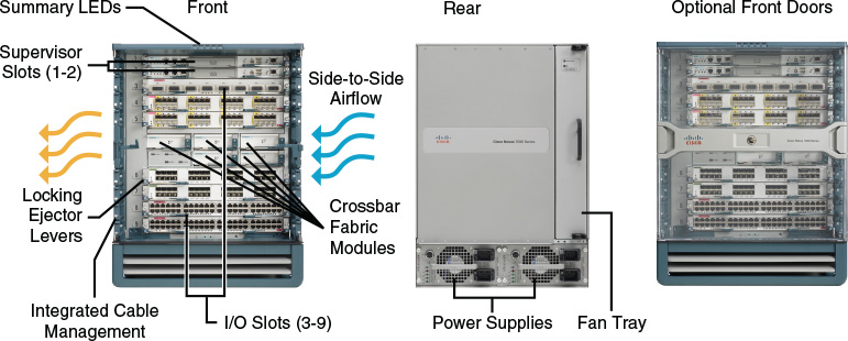
Although the Nexus 7009 has side-to-side airflow, there is a solution for hot aisle–cold aisle design with the 9-slot chassis.
Cisco Nexus 7010 Series Switch Chassis
The Cisco Nexus 7010 switch chassis shown in Figure 1-21 has two supervisor engine slots and eight I/O modules slots; the complete specification is shown in Table 1-5. There are multiple fans on the 7010 system fan trays. The fans on the trays are N+1 redundant. Any single fan failure will not result in degradation in service; the box does not overheat, and the fan tray will need replacing to restore N+1.
Figure 1-21 Cisco Nexus 7010 Switch
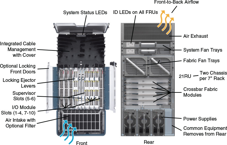
There are two system fan trays in the 7010. If either of the fan trays fails, the system will keep running without overheating as long as the operating environment is within specifications, until the fan tray is replaced. Fan tray replacement restores N+1 redundancy.
There are two fabric fan modules in the 7010; both are required for normal operation. If either fabric fan fails, the remaining fabric fan will continue to cool the fabric modules until the fan is replaced, restoring the N+1 redundancy. The system should not be operated with either the system fan tray or the fabric fan components removed, apart from the hot swap period of up to 3 minutes.
Cisco Nexus 7018 Series Switch Chassis
The Cisco Nexus 7018 switch chassis shown in Figure 1-22 has two supervisor engine slots and 16 I/O module slots; the complete specification is shown in Table 1-5. For the 7018 system, there are two system fan trays—one for the upper half and one for the lower half of the system. Both fan trays must be installed at all times (apart from maintenance). Each fan tray contains 12 fans that are in three rows of four. Each row cools three module slots (I/O and supervisor). The failure of a single fan will result in the other fans increasing speed to compensate, and they will continue to cool the system. The fan tray should be replaced to restore the N+1 fan resilience. Integrated into the system fan tray are the fabric fans. The fabric fans are at the rear of the system fan tray. The two fans are in series so that the air passes through both to leave the switch and cool the fabric modules. Failure of a single fabric fan will not result in a failure; the remaining fan will cool the fabric modules.
Figure 1-22 Cisco Nexus 7018 Switch
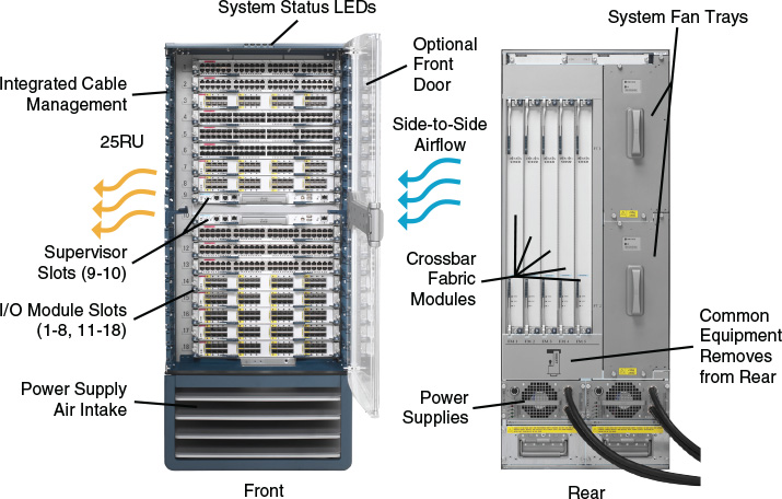
NOTE: Although both system fan trays are identical, the fabric fans operate only when installed in the upper fan tray position. Fan trays are fully interchangeable, but when inserted in the lower position the fabric fans are inoperative.
Cisco Nexus 7706 Series Switch Chassis
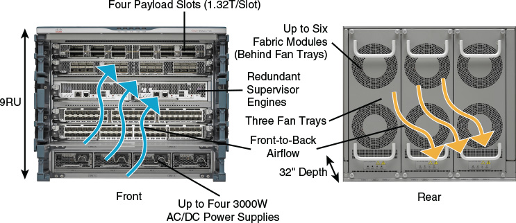
The Cisco Nexus 7706 switch chassis shown in Figure 1-23 has two supervisor module slots and four I/O module slots; the complete specification is shown in Table 1-5. There are 192 10G ports, 96 40G ports, 48 100G ports, true front-to-back airflow, redundant fans, and redundant fabric cards.
Figure 1-23 Cisco Nexus 7706 Switch
Cisco Nexus 7710 Series Switch Chassis
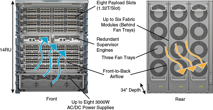
The Cisco Nexus 7710 switch chassis shown in Figure 1-24 has two supervisor engine slots and eight I/O module slots; the complete specification is shown in Table 1-5. There are 384 1-G ports, 192 40-G ports, 96 100-G ports, true front-to-back airflow, redundant fans, and redundant fabric cards.
Figure 1-24 Cisco Nexus 7710 Switch
Cisco Nexus 7718 Series Switch Chassis
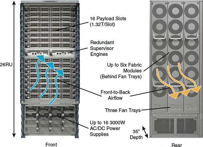
The Cisco Nexus 7718 switch chassis shown in Figure 1-25 has two supervisor engine slots and 16 I/O module slots; the complete specification is shown in Table 1-5. There are 768 10G ports, 384 40G ports, 192 100G ports, true front-to-back airflow, redundant fans, and redundant fabric cards.
Figure 1-25 Cisco Nexus 7718 Switch
Summary
- CISCO NEXUS 7000 SERIES SWITCHES can provide an end-to-end data center architecture on a single platform, including data center core, aggregation, and access layer.
- Cisco Nexus 7000 Series provides high-density 10, 40, and 100 Gigabit Ethernetinterfaces.
- The main features of the Cisco Nexus 7000 Series are: support for FEX, virtual Port Channel (vPC), VDC, MPLS and Fabricpath.
- In addition, the N7K supports fairly robust and established technologies for multi-DC interconnect (DCI) such as OTV and LISP. The N9K does not support these well-established DCI technologies, but a newer DCI technology, VXLAN, BGP, EVPN, that can be deployed for site-to-site DCI.
- The Nexus 7000 series consists of the 7000 and 7700 series switches, the latter being an updated series to the original 7000 series.
- The Nexus 7700 series offers higher bandwidth per slot (1.3Tbps compared to 550Gbps), greater performance and ability to support up to an impressive 192 100GE ports (7700 – 18 slot) compared to 96 100GE ports (7000 – 18 slot).
- The Nexus 7000 is offered in 4, 9, 10 and 18 slot models while the 7700 comes in 2, 6, 10 and 18 slot models.
You can compare all available models at the following URL: https://www.cisco.com/c/en/us/products/switches/nexus-7000-series-switches/models-comparison.html
Info from https://www.ciscopress.com/articles/article.asp?p=2762085&seqNum=2
Video Share: Nexus 7700 shines in 100GE test
Miercom discusses their performance test results of a fully loaded Nexus 7718 switch with 192 100G Ports
More Related
Cisco’s Data Center Architecture
Cisco Nexus 7000 and Nexus 7700 Series Power Supply Options
Cisco Nexus 7000 and Nexus 7700 Supervisor Module
Cisco Nexus Positioning: 2 and 3 Tier
Cisco Nexus 9000 Family: Nexus 9500 Modular Switches and the Nexus 9300 Fixed Configuration


