Cisco IOS IP Service Level Agreements (SLAs) is a part of Cisco IOS that enables customers to assure new business-critical IP applications, as well as IP services that utilize data, voice, and video, in an IP network. Cisco has augmented traditional service level monitoring and advanced the IP infrastructure to become IP application-aware by measuring both end-to-end and at the IP layer.
With Cisco IOS IP SLAs, service provider customers can measure and provide service level agreements, and enterprise customers can verify service levels, verify outsourced service level agreements, and understand network performance. Cisco IOS IP SLAs can perform network assessments, verify quality of service (QoS), ease the deployment of new services, and assist with network troubleshooting.
IP SLAs collects a unique subset of these performance metrics:
- Delay (both round-trip and one-way)
- Jitter (directional)
- Packet loss (directional)
- Packet sequencing (packet ordering)
- Path (per hop)
- Connectivity (directional)
- Server or website download time
Here in this article, we will share an example of using IP SLA to change our default route.

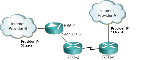
First we create our IP SLA. In this example we want to ping our default gateway of our primary internet connection. In the above diagram that would relate to 11.b.c.d.
ip sla monitor 10
type echo protocol ipIcmpEcho 11.b.c.d
timeout 1000
frequency 3
threshold 2
ip sla monitor schedule 1 life forever start-time now
Next we create a tracked object. This one points to the reachability of the IP SLA. Note that the number 10 relates to the ip sla monitor number.
track 10 rtr 1 reachability
Next we create an ACL. This permits ICMP to our default gateway. This is used in our route map to determine the reachability.
ip access-list 101 permit icmp any host 11.b.c.d echo
Next we create our route map. We macth on the ACL we just created, then set the next hop as the preferred provider IP (11.b.c.d). You must set the interface to null0.
route-map DEFAULT-ROUTE-POLICY permit 10
match ip address 101
set ip next-hop 11.b.c.d
set interface null 0
Next we create a local routing policy to use our newly created route map.
ip local policy route-map DEFAULT-ROUTE-POLICY
Finally we put in our default routes. The first default route points to our preferred provide and we append the tracking to it. We then add the second default route with a higher weight (floating static route). What this does for us is the router will track the preffered default route. If for some reason we lose connectivity (from the IPS SLA) the route will be removed and any secondary default route will be added. In this example the new default route will point to 10.136.5.200
ip route 0.0.0.0 0.0.0.0 11.b.c.d track 10
ip route 0.0.0.0 0.0.0.0 192.168.4.5 200
Let’s take a look at see what happens when we fail over. First let’s check IP SLA and make sure it’s working.
Router#show ip sla statistics
Round Trip Time (RTT) for Index 10
Latest RTT: NoConnection/Busy/Timeout
Latest operation start time: *19:41:46.411 UTC Sun Jul 14 2002
Latest operation return code: Timeout
Number of successes: 233
Number of failures: 0
Operation time to live: Forever
Great, that’s working. Now let’s check the routing table.
Router#show ip route
Codes: C – connected, S – static, R – RIP, M – mobile, B – BGP
D – EIGRP, EX – EIGRP external, O – OSPF, IA – OSPF inter area
N1 – OSPF NSSA external type 1, N2 – OSPF NSSA external type 2
E1 – OSPF external type 1, E2 – OSPF external type 2
i – IS-IS, su – IS-IS summary, L1 – IS-IS level-1, L2 – IS-IS level-2
ia – IS-IS inter area, * – candidate default, U – per-user static route
o – ODR, P – periodic downloaded static route
Gateway of last resort is 11.b.c.d to network 0.0.0.0
10.0.0.0/24 is subnetted, 1 subnets
C 10.1.2.0 is directly connected, Vlan1
S* 0.0.0.0/0 [1/0] via 11.b.c.d
Looks good there. Let’s take a look at the tracking.
Router#show ip route track-table
ip route 0.0.0.0 0.0.0.0 11.b.c.d track 10 state is [up]
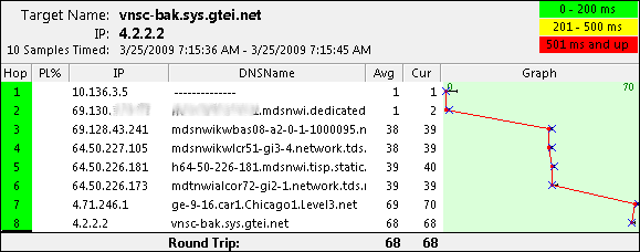
Everything is working when the preferred provider is up. From a client lets do a trace route so we know what way where we’re going.

Now let’s take that circuit down and see if it properly fails over.
*Jul 14 19:47:05.327: %LINEPROTO-5-UPDOWN: Line protocol on Interface FastEthernet0, changed state to down
*Jul 14 19:47:05.327: %LINEPROTO-5-UPDOWN: Line protocol on Interface Vlan1, changed state to down
*Jul 14 19:47:06.331: %LINK-3-UPDOWN: Interface FastEthernet0, changed state to down
*Jul 14 19:47:06.363: %TRACKING-5-STATE: 10 rtr 1 reachability Up->Down
Router#
Let’s take a look at the tracking state.
Router#show ip route track-table
ip route 0.0.0.0 0.0.0.0 11.b.c.d track 10 state is [down]
Router#
Finally let’s check the routing table.
Router#show ip route
Codes: C – connected, S – static, R – RIP, M – mobile, B – BGP
D – EIGRP, EX – EIGRP external, O – OSPF, IA – OSPF inter area
N1 – OSPF NSSA external type 1, N2 – OSPF NSSA external type 2
E1 – OSPF external type 1, E2 – OSPF external type 2
i – IS-IS, su – IS-IS summary, L1 – IS-IS level-1, L2 – IS-IS level-2
ia – IS-IS inter area, * – candidate default, U – per-user static route
o – ODR, P – periodic downloaded static route
Gateway of last resort is 192.168.4.5 to network 0.0.0.0
C 192.168.4.5.0/24 is directly connected, Vlan2
S* 0.0.0.0/0 [254/0] via 192.168.4.5
Router#
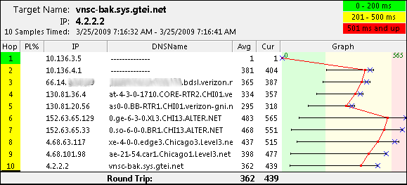
Let’s try another trace route from the client.

Everything is working! Let’s check to make sure when the preferred provider come back on line that we go back to routing out that way.
*Jul 14 19:54:03.395: %LINEPROTO-5-UPDOWN: Line protocol on Interface Vlan1, changed state to up
*Jul 14 19:54:04.387: %LINK-3-UPDOWN: Interface FastEthernet0, changed state to up
*Jul 14 19:54:05.387: %LINEPROTO-5-UPDOWN: Line protocol on Interface FastEthernet0, changed state to up
Router#
Router#
*Jul 14 19:54:41.367: %TRACKING-5-STATE: 10 rtr 1 reachability Down->Up
Router#show ip route track-table
ip route 0.0.0.0 0.0.0.0 11.b.c.d track 10 state is [up]
Router#show ip route
Codes: C – connected, S – static, R – RIP, M – mobile, B – BGP
D – EIGRP, EX – EIGRP external, O – OSPF, IA – OSPF inter area
N1 – OSPF NSSA external type 1, N2 – OSPF NSSA external type 2
E1 – OSPF external type 1, E2 – OSPF external type 2
i – IS-IS, su – IS-IS summary, L1 – IS-IS level-1, L2 – IS-IS level-2
ia – IS-IS inter area, * – candidate default, U – per-user static route
o – ODR, P – periodic downloaded static route
Gateway of last resort is 11.b.c.d to network 0.0.0.0
10.0.0.0/24 is subnetted, 1 subnets
C 10.1.2.0 is directly connected, Vlan1
S* 0.0.0.0/0 [1/0] via 11.b.c.d
Router#
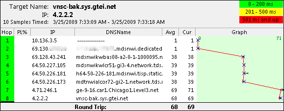
It failed back correctly. A final test from the client workstation and we’re good to go.

Doc Reference from: https://supportforums.cisco.com/docs/DOC-6078
More Related Cisco Network Topics:
Cisco IOS Updates Fix Eight Denial of Service Vulnerabilities
Steps to Configure Static NAT with Route-maps
Basic HSRP Configuration Example On Cisco IOS XR
Conditional Route Origination in OSPF Domain
…


