Spanning Tree Protocol (STP) is a Layer 2 protocol that runs on bridges and switches. The specification for STP is IEEE 802.1D. The main purpose of STP is to ensure that you do not create loops when you have redundant paths in your network. Loops are deadly to a network.
STP runs on bridges and switches that are 802.1D-compliant. There are different flavors of STP, but 802.1D is the most popular and widely implemented. You implement STP on bridges and switches in order to prevent loops in the network. Use STP in situations where you want redundant links, but not loops. Redundant links are as important as backups in the case of a failover in a network. A failure of your primary activates the backup links so that users can continue to use the network. Without STP on the bridges and switches, such a failure can result in a loop. If two connected switches run different flavors of STP, they require different timings to converge. When different flavors are used in the switches, it creates timing issues between Blocking and Forwarding states. Therefore, it is recommended to use the same flavors of STP. Consider this network:
In this network, a redundant link is planned between Switch A and Switch B. However, this setup creates the possibility of a bridging loop. For example, a broadcast or multicast packet that transmits from Station M and is destined for Station N simply continues to circulate between both switches.
However, when STP runs on both switches, the network logically looks like this:
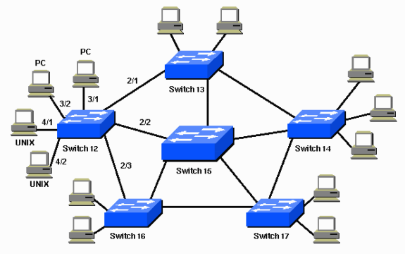
This information applies to the scenario in the Network Diagram:
- Switch 15 is the backbone switch.
- Switches 12, 13, 14, 16, and 17 are switches that attach to workstations and PCs.
- The network defines these VLANs:
- 1
- 200
- 201
- 202
- 203
- 204
- The VLAN Trunk Protocol (VTP) domain name is STD-Doc.
In order to provide this desired path redundancy, as well as to avoid a loop condition, STP defines a tree that spans all the switches in an extended network. STP forces certain redundant data paths into a standby (blocked) state and leaves other paths in a forwarding state. If a link in the forwarding state becomes unavailable, STP reconfigures the network and reroutes data paths through the activation of the appropriate standby path.
Description of the Technology
With STP, the key is for all the switches in the network to elect a root bridge that becomes the focal point in the network. All other decisions in the network, such as which port to block and which port to put in forwarding mode, are made from the perspective of this root bridge. A switched environment, which is different from a bridge environment, most likely deals with multiple VLANs. When you implement a root bridge in a switching network, you usually refer to the root bridge as the root switch. Each VLAN must have its own root bridge because each VLAN is a separate broadcast domain. The roots for the different VLANs can all reside in a single switch or in various switches.
Note: The selection of the root switch for a particular VLAN is very important. You can choose the root switch, or you can let the switches decide, which is risky. If you do not control the root selection process, there can be suboptimal paths in your network.
All the switches exchange information for use in the root switch selection and for subsequent configuration of the network. Bridge protocol data units (BPDUs) carry this information. Each switch compares the parameters in the BPDU that the switch sends to a neighbor with the parameters in the BPDU that the switch receives from the neighbor.
In the STP root selection process, less is better. If Switch A advertises a root ID that is a lower number than the roots ID that Switch B advertises, the information from Switch A is better. Switch B stops the advertisement of its root ID, and accepts the root ID of Switch A.
More Details of STP Operations: STP Configuration Examples Apply to Some Cisco Catalyst Switches like Catalyst 2926G, 2948G, 2980G, 4500/4000, 5500/5000, and 6500/6000 Switches that run Catalyst OS (CatOS)
More Related STP Tips:


