Configuring Virtual Stacking
We have gone through the virtual stacking technology before (Virtual Stacking and Associated Terminologies), its benefits, and how it differs from FlexStack technology on Cisco Catalyst 2960-X Series Switches (FlexStack vs. Virtual Stacking), In this article, we will share step-by-step through configuring a virtual stack.
As discussed in the design consideration section (Requirements for Virtual Stacking), it is recommended that the administrator decides on the switches to be used as commander switch and standby commander switch, respectively, and on the VLAN to be used by the virtual stack domain.
Configuring the commander switch
After the administrator decides on the commander switch and the VLAN to be used, the administrator should assign an IP address to interface.
Catalyst2960L-2009 (config)#int vlan 1

Catalyst2960L-2009 (config-if)#ip address 1.1.1.1

255.255.255.0

Catalyst2960L-2009 (config-if)#no shutdown

Catalyst2960L-2009 (config-if)#exit
After assigning an IP address, configure user name and password, either locally on the switch or through AAA. This user name and password may be shared across all member switches in the virtual domain.
Catalyst2960L-2009 (config)#username commander privilege 15 password secret
After these steps are performed, the switch can be configured to enable clustering
commander_switch(config)#cluster enable <clustername>

<commander no>

Catalyst2960L-2009(config)#cluster enable CorporateCluster 15
Adding member switches to the stack
Now that we have configured virtual stacking on the commander switch, all switches connected to the commander and not configured in a different clustering domain are displayed as cluster candidates.
Catalyst2960L-2009#show cluster candidates

|---Upstream---|

MAC Address Name Device Type PortIf FEC

Hops SN PortIf FEC

2xx2.6xx6.8xx0 Catalyst2960 WS-C2960L-24PS-L Gi1/0/11

1 15 Gi0/11

5xxx.fxxb.axx0 Branch-SW WS-C2960L-24PS-L Gi3/0/16

1 15 Gi0/17

acf2.c56c.1xxx 211 WS-C2960L-24PS-L Gi1/0/7

1 15 Gi0/24

54xx.6xx4.cxxx C2960L-2008 WS-C2960L-24PS-L Gi0/8

2 E Gi1/0/8

8xx5.xxe3.cxx0 Switch WS-C2960L-24PS-L Fa0

2 E Gi1/0/47
Candidate switches can now join the virtual stack by being added to the virtual domain from the commander switch. If they share more than one VLAN in common, the administrator can select the VLAN to be used for the domain.
commander_switch(config)#cluster member <member no>

mac-address <mac address> vlan <vlan>

Catalyst2960L-2009(config)#cluster member 2 mac-address

2xx2.6xx6.8xx0 vlan 1
After a switch is added, observe the console of that member switch for the following log message: Mar 10 10:17:35.164: %CMP-CLUSTER_ MEMBER_2-5-ADD: The Device is added to the cluster (Cluster Name: CorporateCluster, CMDR IP Address 1.1.1.1)
Note: If the password on the member switch differs from that of the commander switch, you will see this error: station %ERROR: password mismatch. In that case, when adding the member to the stack, provide a password for the member switch.
Catalyst2960L-2009(config)#cluster member <member no>

mac-address <mac address> password <password> vlan

<vlan>

Catalyst2960L-2009(config)#cluster member 2 mac-address

2xx2.6xx6.8xx0 password XYZ vlan 1
Verify candidacy of member to the stack
When a member has successfully joined the stack, the administrator can view the candidacy on the commander switch through the command “show cluster members.”
Catalyst2960L-2009#show cluster members

                           |---Upstream---|

SN MAC Address Name PortIf FEC Hops SN PortIf FEC State

2 2xx2.6xx6.8xx0 Catalyst2960 Gi7/0/12 1 15 Gi0/12 Up

15 cxx4.a0xx.xxxx Catalyst2960                  0

Up  (Cmdr)
On the member switch, the “show cluster” command can be executed to find the details about the virtual domain of which the switch is part.
Catalyst2960L#show cluster

Member switch for cluster “CorporateCluster”

               Member number: 2

               Management IP address: 1.1.1.1

Command switch mac address: cxx4.a0xx.xxxx

               Heartbeat interval: 8

               Heartbeat hold-time: 80
Configure and manage stack from commander switch
After having configured and verified the virtual stack, an administrator can configure and manage all the member switches of the stack from one single point.
commander_switch#rcommand where 0-15 is the member number


Catalyst2960L-2009#rcommand 2

Catalyst2960L#show version

Cisco IOS Software, C2960L Software (C2960L-UNIVERSALK9-M),

Version 15.2(6)E, RELEASE SOFTWARE (fc4)

Technical Support: https://www.cisco.com/techsupport

Copyright (c) 1986-2017 by Cisco Systems, Inc.

Compiled Sat 05-Aug-17 12:55 by prod_rel_team
To go back from configuring a member switch to the commander switch, use the keyword “exit” on exec mode.
Catalyst2960L#exit
Catalyst2960L-2009#
Configuring virtual stacking through Cisco Configuration Professional for Catalyst
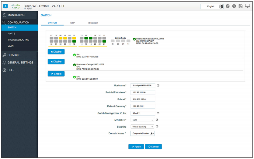
Besides the traditional method of configuring a virtual stack through a CLI, an administrator can also use Cisco Configuration Professional for Catalyst (see Figure1) to configure a virtual stack. Under Configuration > Switch of the web interface for the commander switch, the user can select “Virtual Stacking” as the stacking option and enter the domain name for the cluster.
Figure1. Configuring virtual stacking using Cisco Configuration Professional for Catalyst

After the cluster is created, the web UI will display all possible cluster candidates that the user can add to the virtual stack by clicking “Enable” and entering the password associated with the member switch.
Note: Cisco Configuration Professional for Catalyst release 1.3 and later should be used to configure the virtual stack and for basic management of the member switches.
The reference from https://www.cisco.com/c/dam/en/us/products/collateral/switches/catalyst-2960-x-series-switches/white-paper-c11-739615.pdf
More Related
FlexStack vs. Virtual Stacking
Requirements for Virtual Stacking
Comparison of FlexStack, FlexStack-Plus, and FlexStack-Extended
How to Stack Cisco Catalyst 2960-X or 2960-XR Series Switches?


