
How to Deploy the Cisco ASA FirePOWER Services in the Internet Edge, VPN Scenarios and Data Center? Firstly, you should know the FirePOWER Services for Cisco ASA. Read more: Cisco ASA with FirePOWER Services
Deploying the Cisco ASA FirePOWER Services in the Internet Edge
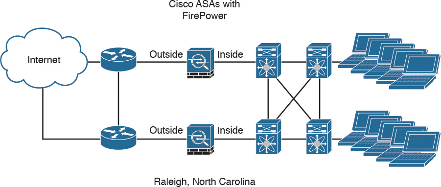
The Cisco ASA FirePOWER module provides unprecedented capabilities to protect a corporate network from Internet threats. Many organizations of all sizes deploy the Cisco ASA FirePOWER module at their Internet edge. The following Figure illustrates a pair of Cisco ASA with FirePOWER modules deployed in the Internet edge of a corporate office in Raleigh, North Carolina.
Cisco ASA FirePOWER Module in the Internet Edge
Deploying the Cisco ASA FirePOWER Services in VPN Scenarios
The Cisco ASA FirePOWER module can be deployed in site-to-site and remote-access VPN environments. As you learned earlier in this chapter, the decryption process takes place before the packets are sent to the Cisco ASA FirePOWER module by the Cisco ASA, and the packets are encrypted after they are inspected by the Cisco ASA FirePOWER module and sent back to the Cisco ASA.
The Figure below illustrates how a Cisco ASA with the FirePOWER module is deployed in an office in New York, terminating SSL and IPsec (IKEv2) VPN tunnels from remote clients in the Internet.
Cisco ASA FirePOWER Module in a Remote-Access VPN Scenario
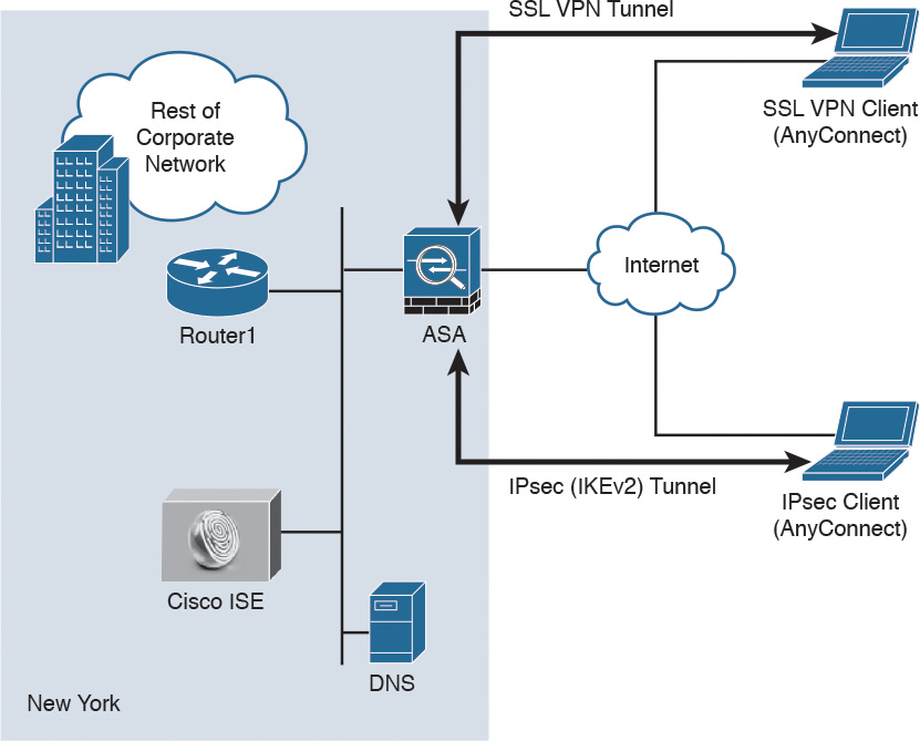
In the example illustrated in Figure above, the remote-access VPN clients are using the Cisco AnyConnect client; however, clientless SSL VPN is also supported.
The following Figure illustrates how two Cisco ASAs with FirePOWER modules are deployed in the headquarters office in New York (ASA 1) and a branch office in Raleigh, North Carolina (ASA 2), establishing a site-to-site IPsec VPN tunnel. In addition, ASA 2 in New York is also terminating a site-to-site IPsec VPN tunnel to a router (R1) of a business partner in Las Vegas.
Cisco ASA FirePOWER Module in a Site-to-Site IPsec VPN Scenario
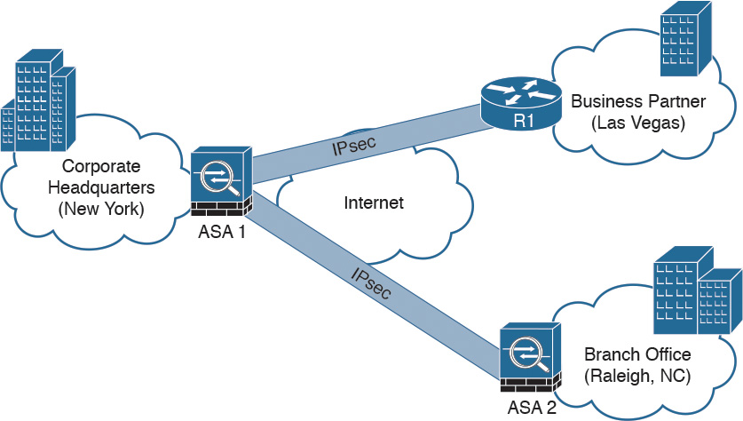
In the example illustrated in Figure above, the Cisco ASA FirePOWER module not only protects against threats in the corporate network in the remote branch office but also protects against threats coming from an unmanaged business partner.
Deploying Cisco ASA FirePOWER Services in the Data Center
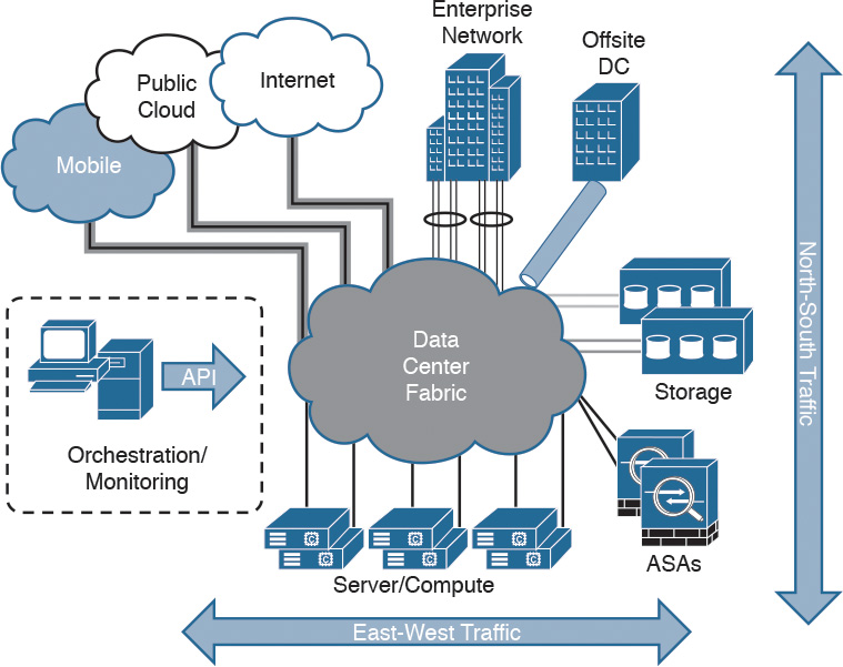
The data center can be a very complex world. It not only provides a rich set of services and architectures but also hosts the crown jewels of an organization. It is extremely important to maintain visibility of everything that is happening in the data center. The concept of “north-to-south” and “east-to-west” is often used in describing the types of communication (or flow) within and to the outside of the data center:
- North-to-south describes communication between end users and external entities.
- East-to-west describes communication between entities in the data center.
The following Figure illustrates the concepts of north-to-south and east-to-west communication.
Data Center North-to-South and East-to-West Communication
The data center has many different high-throughput and low-latency requirements, in addition to increased high-availability requirements. In addition, automated provisioning and control with orchestration, monitoring, and management tools are crucial.
The data center architecture consists of three primary modular layers with hierarchical interdependencies:
- Data center foundation: This is the primary building block of the data center, on which all other services rely. Regardless of the size of the data center, the foundation must be resilient, scalable, and flexible to support data center services that add value, performance, and reliability. The data center foundation provides the computing necessary to support the applications that process information and the seamless transport between servers, storage, and the end users who access the applications.
- Data center services: These services include infrastructure components to enhance the security of the applications and access to critical data. They also include virtual switching services to extend the network control in a seamless manner from the foundation network into the hypervisor systems on servers to increase control and reduce operational costs (as well as other application resilience services).
- User services: These services include email, order processing, and file sharing or any other applications in the data center that rely on the data center foundation and services, like database applications, modeling, and transaction processing.
The Figure below illustrates some of the components of the data center services architecture.
The Data Center Services Architecture
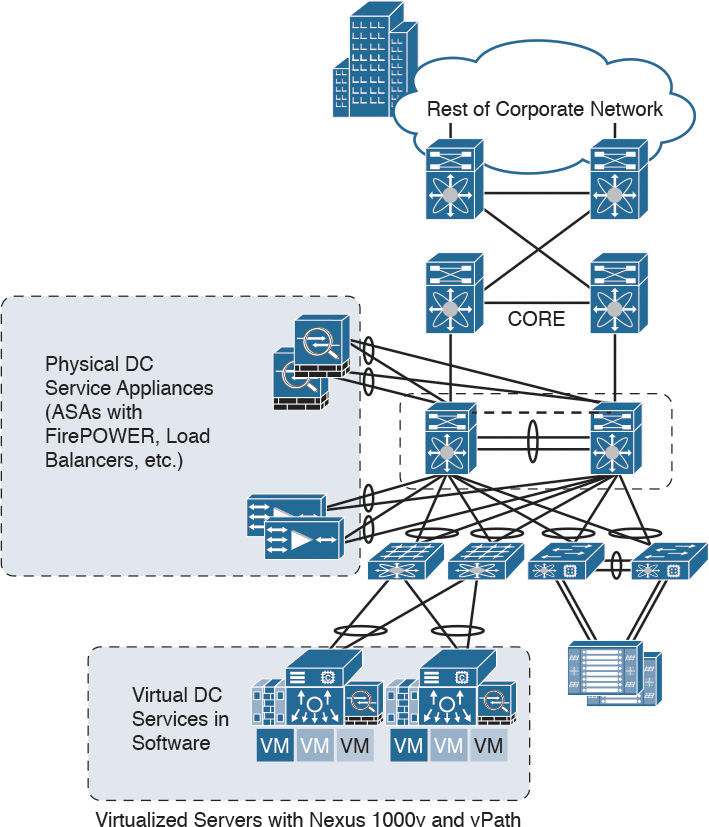
Examples of the data center service insertion components include the following:
- Firewalls (In the example illustrated in the following Figure, Cisco ASAs with FirePOWER modules are deployed.)
- Intrusion prevention systems (IPS)
- Application delivery features
- Server load balancing
- Network analysis tools (such as NetFlow)
- Virtualized services deployed in a distributed manner along with virtual machines
- Traffic direction with vPath and Nexus 1000v
- Application Centric Infrastructure (ACI) automated framework components for service insertion
In the case of virtualized environments, the Cisco ASAv (virtual machine) can be deployed to protect VM-to-VM communication. The Cisco ASA FirePOWER module in these environments is not supported, as the Cisco ASAv is just a virtual machine. Cisco FirePOWER virtual machines running network AMP can be deployed in those scenarios.
NOTE: The Cisco ASAv supports both traditional tiered data center deployments and the fabric-based deployments of Cisco ACI environments. The Cisco ASAv can also be deployed in cloud environments like Amazon Web Services (AWS).
The Cisco ASA with FirePOWER modules can be deployed in geographically dispersed cluster environments.
The Figure below shows an example in which four Cisco ASAs with FirePOWER modules are deployed in two separate sites (site A and site B).
Cisco ASA FirePOWER Module in a Geographically Dispersed Data Center
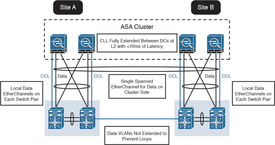
In the example illustrated in the Figure above, the cluster of four Cisco ASAs is fully extended between the two data centers, using the cluster control links (CCL) operating at Layer 2 with a latency of less than 10 milliseconds. A single spanned EtherChannel for transient data is used on the cluster side. The local data links are also configured with EtherChannels at the switch pairs on each site.
TIP: The data VLANs between the switches are not extended to prevent network loops.
Reference from https://www.ciscopress.com/articles/article.asp?p=2730336&seqNum=12
More Related
The Most Common NGFW Deployment Scenarios


